Building a model
Note
The information below is incomplete. Deltares is working on a tutorial.
Data requirements
The actual data requirements depend on the application of the model. The following list summarizes the data requirements:
Static data
Digital Elevation Model (DEM)
A Land Cover map
A map representing Soil physical parameters (the Land Cover map can also be used)
Dynamic data (spatial time series, map-stacks)
Precipitation
Potential evapotranspiration
Temperature (optional, only needed for snow pack modelling)
Model parameters (per land use/soil type)
Soil Depth
etc… (see Input parameters (lookup tables or maps))
The module can be linked to the Delft-FEWS system using the general adapter. The model itself comes with the necessary reading/writing routines for the Delft-FEWS pi XML files. An example of the link to Delft-FEWS is given in section wflow_adapt Module
In addition, each model should have an ini file (given the same basename as the model) that contains models specific information but also information for the framework (see wf_DynamicFramework)
Setting-up a new model
Setting-up a new model first starts with making a number of decisions and gathering the required data:
Do I have the static input maps in pcraster format (DEM ,land-use map, soil map)?
What resolution do I want to run the model on?
Do I need to define multiple sub-catchments to report totals/flows for seperately?
What forcing data do I have available for the model (P, Temp, ET)?
Do I have gridded forcing data or scalar time-series?
Note
Quantum Gis (QGIS) can read and write pcraster maps (via gdal) and is a very handy tool to support data preparation.
Note
Within the earth2observe project tools are being made to automatically download and downscale reanalysis date to be used as forcing to the wflow models. See https://github.com/earth2observe/downscaling-tools
Depending on the formats of the data some converting of data may be needed. The procedure described below assumes you have the main maps available in pcraster format. If that is not the case free tools like Qgis (www.qgis.org) and gdal can be used to convert the maps to the required format. Qgis is also very handy to see if the results of the scripts match reality by overlaying it with a google maps or OpenStreetMap layer using the qgis openlayers plugin.
When all data is available setting up the model requires the following steps:
Run the wflow_prepare_step1 and 2 scripts or prepare the input maps by hand (see Preparing static input maps)
Setup the wflow model directory structure (Setup a case) and copy the files (results from step2 of the prepare scripts) there (see Setting Up a Case)
Setup the .ini file
Test run the model
Supply all the .tbl files (or complete maps) for the model parameters (see Input parameters (lookup tables or maps))
Calibrate the model
Preparing static input maps
Introduction
Preparing the input maps for a distributed model is not always trivial. wflow comes with two scripts that help in this process. The scripts are made with the assumption that the base DEM you have is a higher resolution as the DEM you want to use for the final model. When upscaling the scripts try to maintain as much information from the high resolution DEM as possible. The procedure described here can be used for all wflow models (wflow_sbm or wflow_hbv).
Using the scripts
The scripts assume you have a DEM, landuse and soil map available in pcraster format. If you do not have a soil or landuse map the you can generate a uniform map. The resolution and domain of these maps does not need to be the same, the scripts will take care of resampling. The process is devided in two scripts, wflow_prepare_step1.py and wflow_prepare_step2.py. In order to run the scripts the following maps/files need to be prepared.
Note
Both scripts need pcraster and gdal executables (version >= 1.10) to be available in your computers search path
a DEM in pcraster format
a land use map in pcraster format. If the resolution is different from the DEM the scripts will resample this map to match the DEM (or the DEM cutout). If no landuse map is found a uniform map will be created.
a soil map in pcraster format. If no soil map is found a uniform map will be created.
a configuration file for the prepare scripts that defines how they operate (.ini format) file (see below)
an optional shape file with a river network (you can usually get one out of OpenStreetMap)
an optional catchment mask file
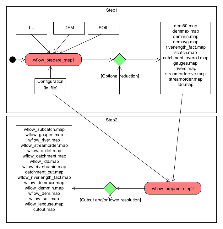
The scripts work in two steps, each script need to be given at least one command-line option, the configuration file. The first script performs the following tasks:
wflow_prepare_step1.py
Performs an initial upscaling of the DEM if required (set in the configuration file). This initial upscaling may be needed if the processing steps (such as determining the drainage network) take a very long time or if the amount of available memory is not sufficient. The latter may be the case on 32bit systems. For example a 90x90 m grid for the Rhine/Meuse catchment could not be handled on a 32 bit system.
Create the local drainage network. If the ldd is already present if will use the existing ldd. Use the force option to overwrite an existing ldd.
Optionally use a shape file with a river network to “burn-in” this network and force the ldd to follow the river. In flat areas wher the river can be higher than the surrounding area having a river shape is crucial.
Tip
Another option is to prepare a “pseudo dem” from a shape file with already defined catchment boundaries and outlets. Here all non boundary points would get a value of 1, all boundaries a value of 2 and all outlets a value of -10. This helps in generating a ldd for polder areas or other areas where the topography is not the major factor in determining the drainage network.
Determine various statistics and also the largest catchment present in the DEM. This area will be used later on to make sure the catchments derived in the second step will match the catchment derived from the high resolution DEM
wflow_prepare_step2.py
Create a map with the extend and resolution defined in the configuration file and resample all maps from the first step to this resolution
Create a new LDD using the following approach:
Construct a new dem to derive the ldd from suing the minimum dem from the first step for all the pixels that are located on a river and the maximum dem from the first step for all other pixels.
In addition raise all cells outside of the largest catchment defined in the first step with 1000 meter divided by the distance of each cell to the largest catchment.
Derive the ldd and determine the catchments
Steps in creating the wflow model input
Once the script is finished successfully the following maps should have been created, the data type is shown between brackets:
wflow_catchment.map (ordinal)
wflow_dem.map (scalar)
wflow_demmax.map (scalar)
wflow_demmin.map (scalar)
wflow-dem*percentile* - (10,25,33,50,66,75,90) (scalar)
wflow_gauges.map (ordinal)
wflow_landuse.map (nominal)
wflow_soil.map (nominal)
wflow_ldd.map (ldd)
wflow_outlet.map (scalar)
wflow_riverburnin.map (boolean)
wflow_riverlength_fact.map (scalar)
wflow_river.map (ordinal)
wflow_streamorder.map (ordinal)
wflow_subcatch.map (ordinal)
The maps are created in the data processing directory. To use the maps in the model copy them to the staticmaps directory of the case you have created.
Note
Getting the subcatchment right can be a bit of a problem. In order for the subcatchment calculations to succeed the gauges that determine the outlets must be on a river grid cell. If the subcatchment creation causes problems the best way to check what is going on is to import both wflow_gauges,map en wflow_streamorder.map in qgis so you can check if the gauges are on a river cell. In the ini file you define the order above which a grid cell is regarded as a river.
Note
If the cellsize of the output maps is identical to the input DEM the second script shoudl NOT be run. All data will be produced by the first script.
Command line parameters
Both scripts take the same command-line parameters:
wflow_prepare_step1 -I inifile [-W workdir][-f][-h]

    -f force recreation of ldd if it already exists
    -h show this information
    -W set the working directory, default is current dir
    -I name of the ini file with settings
contents of the configuration file for the preprocessing
An example can be found here.
[directories]
# all paths are relative to the workdir set on the command line
# The directories in which the scripts store the output:
step1dir = step1
step2dir = step2

[files]
# Name of the DEM to use
masterdem=srtm_58_14.map
# name of the lad-use map to use
landuse=globcover_javabali.map
soil=soil.map
# Shape file with river/drain network. Use to "burn in" into the dem.
river=river.shp
riverattr=river
# The riverattr above should be the shapefile-name without the .shp extension

[settings]
# Nr to reduce the initial map with in step 1. This means that all work is done
# on an upscaled version of the initial DEM. May be usefull for very
# large maps. If set to 1 (default) no scaling is taking place
initialscale=1

# Set lddmethod to dem (other methods are not working at the moment)
lddmethod=dem

# If set to 1 the gauge points are moved to the neares river point on a river
# with a strahler order higher of identical as defined in this ini file
snapgaugestoriver=1

# The strahler order above (and including) a pixel is defined as a river cell
riverorder=4

# X and y cooordinates of gauges (subcatchments). Please note the the locations
# are based on the river network of the DEM used in step2 (the lower resuolution
# DEM). This may need some experimenting... is most case the snap function
# will work by ymmv. To set multiple gauges use x_gauge_1, x_gauge_2

gauges_y = -6.1037
gauges_x = 107.4357


# settings for subgrid to create. This also determines how the
# original dem is (up)scaled. If the cellsize is the same
# as the original dem no scaling is performed. This grid will
# be the grid the final model runs on
Yul = -6.07
Xul = 106.9
Ylr = -7.30271
Xlr = 107.992
cellsize = 0.009166666663

# tweak ldd creation. Default should be fine most of the time
lddoutflowdepth=1E35
lddglobaloption=lddout
# use lddin to get rid of small catchments on the border of the dem
Problems
In many cases the scripts will not produce the maps the way you want them in the first try. The most common problems are:
The gauges do not coincide with a river and thus the subcatchment is not correct
Move the gauges to a location on the rivers as determined by the scripts. The best way to do this is to load the wflow_streamorder.map in qgis and use the cursor to find the nearest river cell for a gauge.
The delimited catchment is not correct even if the gauges is at the proper location
Get a better DEM or fix the current DEM.
Use a river shape file to fix the river locations
Use a catchment mask to force the catchment delineated to use that. Or just clip the DEM with the catchment mask. In the latter case use the lddin option to make sure you use the entire catchment.
If you still run into problems you can adjust the scripts yourself to get better results.
Script documentation
wflow_prepare_step1
wflow data preparation script. Data preparation can be done by hand or using the two scripts. This script does the first step. The second script does the resampling. This scripts need the pcraster and gdal executables to be available in you search path.
Usage:
wflow_prepare_step1 [-W workdir][-f][-h] -I inifile

-f force recreation of ldd if it already exists
-h show this information
-W set the working directory, default is current dir
-I name of the ini file with settings
$Id: $
- wflow_prepare_step1.OpenConf(fn)
- wflow_prepare_step1.configget(config, section, var, default)
gets parameter from config file and returns a default value if the parameter is not found
- wflow_prepare_step1.main()
- Variables:
masterdem – digital elevation model
dem – digital elevation model
river – optional river map
- wflow_prepare_step1.usage(*args)
wflow_prepare_step2
wflow data preparation script. Data preparation can be done by hand or using the two scripts. This script does the resampling. This scripts need the pcraster and gdal executables to be available in you search path.
Usage:
wflow_prepare_step2 [-W workdir][-f][-h] -I inifile
-f force recreation of ldd if it already exists
-h show this information
-W set the working directory, default is current dir
-I name of the ini file with settings
$Id: $
- wflow_prepare_step2.OpenConf(fn)
- wflow_prepare_step2.configget(config, section, var, default)
- wflow_prepare_step2.main()
- wflow_prepare_step2.resamplemaps(step1dir, step2dir)
Resample the maps from step1 and rename them in the process
- wflow_prepare_step2.usage(*args)
Setting Up a Case
PM
Note
Describes how to setup a model case structure. Probably need to write a script that does it automatically.
See wf_DynamicFramework for information on the settings in the ini file. The model specific settings are described seperately for each model.
Input parameters (lookup tables or maps)
The PCRaster lookup tables listed below are used by the model to create input parameter maps. Each table should have at least four columns. The first column is used to identify the land-use class in the wflow_landuse map, the second column indicates the subcatchment (wflow_subcatch), the third column the soil type (wflow_soil.map) and the last column list the value that will be assigned based on the first three columns.
Alternatively the lookup table can be replaced by a PCRaster map (in the staticmaps directory) with the same name as the tbl file (but with a .map extension).
Note
Note that the list of model parameters is (always) out of date. Getting the .tbl files from the example models (default_sbm and default_hbv) is probably the best way to start. In any case wflow will use default values for the tbl files that are missing. (shown in the log messages).
Below the contents of an example .tbl file is shown. In this case the parameters are identical for each subcatchment (and soil type) but is different for each landuse type. See the pcraster documentation (http://www.pcraster.eu) for details on how to create .tbl files.
1   <,14]   1 0.11
2   <,14]   1 0.11
3   <,14]   1 0.15
4   <,14]   1 0.11
5   <,14]   1 0.11
6   <,14]   1 0.11
Note
please note that if the rules in the tbl file do not cover all cells used in the model you will get missing values in the output. Check the maps in the runid/outsum directory to see if this is the case. Also, the model will generate a error message in the log file if this is the case so be sure to check the log file if you encounter problems. The message will read something like: “ERROR: Not all catchment cells have a value for…”